| This is a child page. You can use Parent in the quick nav bar at the top or the bottom of the page to navigate directly back to the parent of this page. Some child pages are more than one level deep, and in that case will require more than one Parent click to reach the outermost document level. |
§ 16.90.6.2 - What is Ray Tracing?
Ray tracing is best described as a special effects operation that can produce photo-realistic images. By photo-realistic, we mean that object's interaction with light and the observer obey laws similar to the laws of physics we observe in the real world.
That definition is a little simplistic. Ray Tracing doesn't behave exactly as our vision behaves. This difference is subtle — but critical — to the concepts of Ray Tracing. We'll expand on the above definition a little further on, but it will do for now.
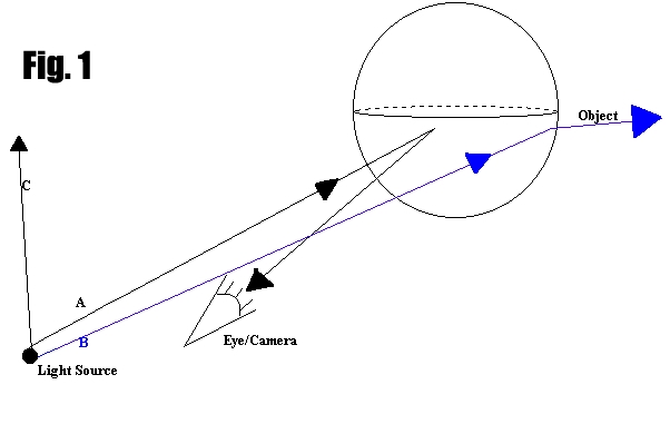
Imagine first, a simplified situation [fig. 1] (we'll even Ray Trace this example a little later), where a red ball is found floating amongst nothing else, a complete void. Somewhere behind the "camera" is a light source. We will use rays to model "beams of light" or photons, they will also be referred to as "rays of light."
It's important to observe that some rays, like A in the example, will reflect back toward the eye, and thus will be seen. Other rays, like B, will reflect away from the eye. This is especially pronounced as the surface of the object curves away from the light source, these rays will not hit the eye and will not be seen. As more and more of the rays are deflected away, the surface will become darker and darker.
Other rays that do not come into contact with the object, C for example, fall under a special case. These rays are of no consequence to the area being viewed. These will constitute most of the rays leaving the light source.
We say "most of the rays" because this figure is grossly simplified, a myriad of rays are leaving the light source at any given time. These rays leave in every direction, thus we observe an all-encompassing effect from the light.
Considering the example above, such a model would consume tremendous computing resources. Most of those resources would be spent on aspects of the model that won't even be shown in the image — light rays that intersect no object and those which would not reach the viewer's eye.
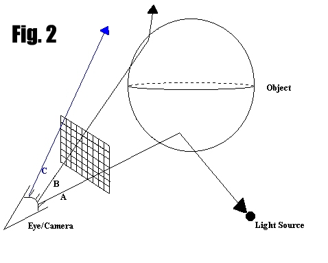
To simplify the computing task, the tracing is reversed, as shown in Fig. 2. This method is known as "Reverse Ray Tracing," and is the method by which most Ray Tracing programs compute their results. F/x is no exception.
Instead of modeling every ray that leaves the light, paths are computed from the imaginary camera through the pixels on the screen until an object is intersected (rays A and B) or it leaves the scope of the model(C). If necessary, the angle from the point the ray intersects to the light is determined, and it is also determined if the light from the source would be blocked or otherwise disturbed. The coloration of the point (the pixel on the screen) is determined accordingly. Ray A would be lit brightly because it traces a relatively direct path to the light source. Ray B would be shaded because some of the light would be blocked by the curvature of the sphere.
This approach simplifies the matter because only aspects which directly affect the image produced will be rendered. This brings the complexity of the operation down significantly but make no mistake, Ray Tracing is a complex and time-consuming operation.
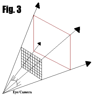
For clarity's sake, the "viewing frustrum" is the bounds in which the Ray Tracer's "eye" can see from it's location. A frustum is like a pyramid that never ends. Figure 3 is a diagram of the viewing frustrum.
The pyramid shape is determined by how the viewpoint (eye) intersects the edges of the screen, as shown.
For the purposes of ray tracing, the base of the pyramid (red line) can be defined as the beginning of the region that contains no objects to be traced.
Now that you have a basic understanding of how the camera "sees," lets take an exploratory look at just how the "red ball" example would be implemented in F/x's SceneScript here.
, Previous Page . Next Page t TOC i Index o Operators g Glossary
Copyright © 1992-2007 Black Belt Systems ALL RIGHTS RESERVED Under the Pan-American Conventions
WinImages F/x Manual Version 7, Revision 6, Level A
![]()