| This is a child page. You can use Parent in the quick nav bar at the top or the bottom of the page to navigate directly back to the parent of this page. Some child pages are more than one level deep, and in that case will require more than one Parent click to reach the outermost document level. |
§ 16.15 - Radial Wave
| Quick Reference to Scripting Command |
| a=RADWAVE(distortion, frequency, halfwaves, radius, phase, shading) |
| Items in CAPS are 0/1 or ranges with more options than just 0/1. Ranges other than 0/1 are indicated by brackets, such as [0-2]. |

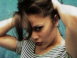 Original Image |
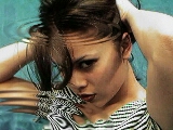 Radial Waves |
This operator may be applied directly to a Warp Layer, resulting in a geometric effect that may be removed from the underlying sublayer composite by simply zeroing out the warp or disabling that layer. In addition, the effect may be moved over the underlying sublayer composite without limit.
A visual reminder that this operator is warp-compatible is the small green dot at the upper right of its ICON in the toolbar.
The Radial Wave operation allows you to apply an effect similar to dropping a stone into a still pool of water. You have control over the Distortion, Frequency, Number of Half Waves, Radius, Phase, and Shading. This operation requires an Undo Buffer. If you do not have an Undo buffer allocated, WinImages F/x will automatically allocate one for you. This operation is best suited for use with the ellipse area selection tool due to its circular nature.
One of the advantages of the Radial Wave operation is that it will work with any elliptical area selection. Very realistic "perspective" effects may be created simply by using a flatter ellipse, rather than a more circular selction. This is demonstrated in the sample images above.
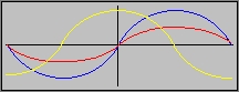
Peak/Crest: A Peak or Crest is the maximum positive value of the wave. This maximum value is determined by the Amplitude of the wave, and is equal to the Trough maximum value. The diagram above shows a peak for each of the three waves.
Trough: A Trough is the maximum negative value of the wave. This maximum is determined by the Amplitude of the wave, and is equal to Peak or Crest maximum value. The diagram above shows a trough for the Red and Blue waves, and the beginning of two separate troughs for the Yellow wave.
Amplitude: Amplitude is the maximum positive and negative displacement of the wave. The diagram above shows three waves; Red, Blue, and Yellow. The Yellow and blue waves both have the same amplitude or vertical displacement. The Red wave has one half the amplitude of the other two waves. The amplitude control is called Distortion %, and its use is discussed in the main documentation for the Radial Wave operation.
Frequency: Frequency is the number of waves over a certain amount of time. In WinImages F/x the Frequency is the number of waves per distance. The Frequency can be altered using the Frequency control.
Half Waves: An individual wave is composed of two Half Waves. These Half Waves are the positive and negative maximum amplitudes of the wave. The number of Half Waves in a Radial Wave is set using the Half Waves control.
Phase: The Phase of a wave deals with the relative position of the wave at a given moment in time. In the diagram above.
§ 16.15.1 - Radial Wave Controls
§ 16.15.1.1 - Trends
Operator dialog controls that have a Trend button next to them offer animation functionality. Trend allows you to set that variable over a set of frames. Each frame of the animation can be thought of as a slice of time. The trends allow you to alter some, all, or none of the variables for a particular time slice. Variables that have multiple states can be set to any of a number of values in the trend. Variables that are either on or off can only have an on or off value in the trend. You will notice that the trend graphs have equidistantly spaced vertical lines. Each of these lines represents a frame in the animation. The number of frames can be altered using Sequence controls... in the TimeLine pull down menu. Animation lengths of 100 - 999 frames will be represented with a vertical bar being 10 frames, and animation length greater than 1000 frames will have a vertical bar for every 100 frames. Click here to view more information on Trends.
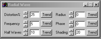
§ 16.15.1.2 - Distortion %
The Distortion percentage can be considered the amplitude of the wave. The Distortion settings range from 0% to 100%. Setting the Distortion% to 100% will result in the maximum amplitude for each Half Wave. The amplitude of the half waves decreases as the distortion setting decreases. The control can be set using the slide gadgets or by entering the appropriate value in the provided text entry field.
§ 16.15.1.3 - Frequency
Frequency is the total number of waves that can appear in the selected area. The Frequency setting can range from 0 to 100. A setting of 0 will result in no change to the image. The frequency control can be set using the slide gadget or by entering the appropriate value in the provided text entry field.
§ 16.15.1.4 - Half Waves
The Half Waves setting controls how many Half Waves (peaks and troughs) will appear in the selected area based on the Frequency setting. A complete wave is made up of two portions; a peak and a trough. The peak is the maximum positive amplitude of the wave, and the trough is the maximum negative amplitude. For example, a wave with a frequency of 12 would have 24 half waves. The Half Waves setting can be altered by using the slide gadget or by entering the appropriate value in the provided text entry fields.
§ 16.15.1.5 - Radius
The Radius control allows you to specify where the waves will start relative to the center of the area selection. The radius is set up as a percentage value with 0 being 0 % (center of area select) and 1000 being 100% (edge of area select). Setting the control to 1000 will result in no wave with some area selection methods. The Radius setting can be altered using its slide gadget or by entering the desired value in the provided text entry field.
§ 16.15.1.6 - Phase
The Phase control allows you to alter the waves relative position at a certain time. The control ranges from 0 to 360 degrees. For example, by altering the Phase from 0 to 90 degrees will cause the peaks and troughs to trade their positions. The Phase can be set using the slide gadget or by entering the appropriate value in the text entry area.
Altering the Phase in large degrees, over a series of frames, may cause tearing or discontinuities in the image.
§ 16.15.1.7 - Shading
The Shading control allows you to set the degree of shading in the waves. The control ranges from 0% to 100%. A setting of 0% will result in a wave that has no shading in the troughs, and a setting of 100% will result in a wave with the maximum amount of shading in the troughs. The control can be altered using the slide gadget or by entering the proper value in the text entry field.
, Previous Page . Next Page t TOC i Index o Operators g Glossary
Copyright © 1992-2007 Black Belt Systems ALL RIGHTS RESERVED Under the Pan-American Conventions
WinImages F/x Manual Version 7, Revision 6, Level A
![]()