| This is a child page. You can use Parent in the quick nav bar at the top or the bottom of the page to navigate directly back to the parent of this page. Some child pages are more than one level deep, and in that case will require more than one Parent click to reach the outermost document level. |
§ 27.18.2 - Warp Morphing - The Basics
The simplest way to familiarize yourself with Morph (and morphing in general), is to simply start creating morphs. we will begin this tutorial with the simplest type of morphing: warp morphing or warping. This type of morphing uses a single image with two distinct sets of points or Objects. These points or Objects are set around features in the Start image, and the exaggerated or moved in the End image to create a "warped" effect. Warp morphing is the least complex of the various morphing operations, and working with it will provide a good general understanding of the basic tools available for all types of morphing within the application.
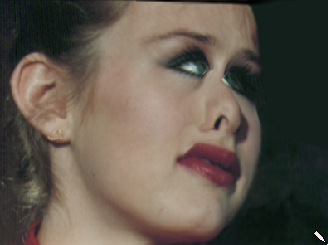
The first step in creating a warp morph is to load the image that you wish to morph. This can be accomplished by accessing the File menu's Load Start Frame... option. For this example you will want to load the firegirl.trm image file located in your C:\Images directory. Morph will automatically identify the image file type, and load the image into the Start Image View Window. We will now need to place the same image in the End Image View so that we have both a start and end image. This can be done by selecting the File menu's Load End Frame... option, or by selecting the Distortion Morph option from the Settings menu. The latter method will simply clone the existing start image into the End Image View window.
The Morph interface consists of five separate control elements:
This tutorial assumes that you have read the information in the previous tutorial section.
Each of these Control elements are used to create a morph. In the Morph program window, you should see two View windows with the firegirl.trm image in both, the FilmStrip, and the Toolbox.
This tutorial will begin by showing you how to use Control Points, proceed to using Links, and then finally the Ellipse.
Although the Ellipse produces the best results in the tutorial, you should not skip the steps for using Control Points and Links, as you'll definitely need those skills later on.
We will begin by specifying a series of points on and around the left eye of the girl in the Start image. This is done by first selecting the point tool from the Toolbox, and then clicking with the left mouse button where you would like the Control Points to appear. The Control Points specify areas of the image that you would like to "focus" control on. This Control Point also has a corresponding Control Point in the End Image.
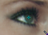
Start specifying Control Points by left clicking while the pointer is over center of the girl's eye. You should see a small blue cross appear where you clicked (this color can vary based on your display settings). Now, look in the End image; you should see a matching Control Point in that image in exactly the same location on the End image.
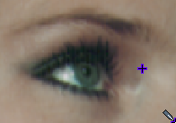
Now, use the right mouse button to drag the end Control Point in the End Image somewhat off-center (if you're using the face that we suggested, drag it to the right of the eye about the width of the eye). What you have done is told Morph that the part of the image identified by that Control Point on the start image (the starting location) is to be moved, or distorted, to the location indicated by the ending Control Point.
Let's take a look and see what kind of results you get from this single Control Point. In this case we will want to generate only one frame.
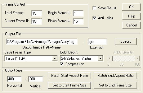
This can be accomplished by entering the Sequence Controls dialog to specify the frame we want generated, and the resolution that it should appear as. The Sequence Controls dialog can be accessed by selecting Sequence Controls... in the Generate menu. This dialog contains a number of controls that affect the output frames of a morph sequence.
For this example, we will want to set the Total Frames control to 15, and the Current Frame # option to 15 as well. This tells Morph that we would like to move the points and Objects from their start position to their end position over 15 frames. These settings also tell the program that when a single frame is to be generated, that we would like the final frame of the output.
There are several other controls for altering the morphing method, saving, output file type, and output size. All of these controls are documented in the section related to the Sequence Controls dialog. The final two controls that we will want to set are the ✓ Save Results control and the Output Size parameters. For this example morph, you will not want to save the results. This can be set be making sure that the ✓ Save Results check box is not selected. If this control is selected, then each output frame created by Morph will be saved in the output file type specified in the middle section of the Sequence Controls dialog; but we're not going to save our results yet.
The other option that we need to set is the Output Size, or resolution. This size automatically defaults to 96x72, which is the FilmStrip resolution. This is done so that preview morphs can be quickly generated, and then edited until a final result is ready for generation. In all most all cases you will want to increase this resolution for your final output frames. In this case we want to clearly see in the Result Image View the 15th frame. The low resolution settings (96x72) will not be clear enough to view the changes we made to the image. The resolution can be set to any custom width or height, or you may select the resolution based on the Start or End image View's resolution or aspect ratio.
For this example, we want to select Set to Start Frame Size. This will cause Morph to generate the output in the same resolution as the Start frame or image. In this case that resolution is 300x400 pixels.
We have now completed setting up the output requirements for this first morphing test. Select OK at the top of the dialog to confirm these changes. The next step in generating a single frame is to select the Do one frame... option from the Generate menu. This will tell Morph that you would like to generate the current frame based on the Control Points and Objects.
As the morph frame is generated, a progress bar will indicate how far the morph operation has to go to completion. On a modern machine, this should happen very quickly. When the morph completes, the morphed image will be drawn in the Result Image View. Depending on just how far you moved the end point, the morphed image may look slightly distorted, or very distorted.
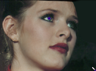 Original |
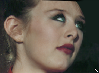 Result |
Now, add a second start point by clicking on the Start Image View, and again move the corresponding end Control Point. Put the new start Control Point in the middle of the other (right) eye and drag the end Control Point on End Image to the left of the eye, again by about the width of the eye:
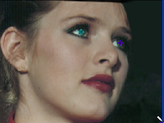 Start Frame |
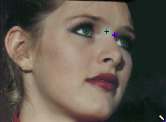 End Frame |
Let's see how this new Control Point affects the morph. The frame can be generated by selecting the Do one frame... option from Generate menu. Morph will now re-generate the Result morph:
You should be getting the idea now; many unique and interesting warp morphs can be specified using Control Points just the way we've been showing you. These same basic principles can be used with other control Objects (lines & curves) to create more complex movements and distortions.
Usually, a large number of Control Points are used to completely specify the exact distortions required. These Control Points can easily be replaced with lines or curves of control. It is important to remember that the more Control Points or lines you use, the better the resulting morph will be. For the best results, you would completely outline features you want to change (like the eyes) and then change the endpoints in the end view to represent the new form you want the image to take. The Start Image View contains the same image as the End Image View so you have a reference of just how far to go, or how much distortion you want.
We'll go through a quick example of this and in the process teach you how to use Links and a few more of the morphing tools. First, you'll want to delete all of the points you've already placed. There are two ways you can do this:
-
Use the ← and → keys to select each Control Point in turn, then press the Del key. In this fashion, you can remove Control Points one by one. You'll do this a lot in more complex morphs, so it's important to be familiar with this method.
-
To clear out all Points, Links and Objects in one step, you enter the Objects pull down menu, and select the Delete Objects option. Morph will automatically delete all of the Control Points and Objects on both the Start and End image Views.
In most cases, you will want to save your Control Point set before deleting it. Probably not this time, though.
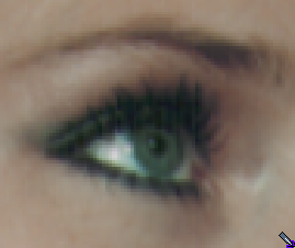
Next, since we're going to be doing a bit more of an exacting operation, let's Zoom in on the area where we'll be working, the left eye. To Zoom, first click on the Zoom button located in the top right-hand corner of Morph's Toolbar. You will notice that the normal Morph pointer will change into the shape of a magnifying glass. You should now point the Zoom pointer about 1/2 inch above and to the left of the left eye, click and hold the left mouse button and drag the mouse down and to the right. A box will appear; keep pulling until the box entirely encloses the eye (about 1/2 inch below and right) and then let go of the mouse button. The Zoom Box can be repositioned by pressing the right mouse button in addition to the left.
The area could also be Zoomed by left clicking the mouse with the cursor over the center of the area that you would like to Zoom. This will cause Morph to do a simple 2x Zoom with the cursor position as the center.
The image will now be Zoomed in:
If the result is not very similar to the above, click on the De-Zoom button (that's actually the bottom left of the Zoom button) and the zoom will be turned off. Repeat these steps, beginning with re-selecting the Zoom button, to get a better Zoom around both the Start and the End image eye. When you have both the Start and End image eyes nicely centered in a Zoomed image, continue.
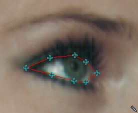
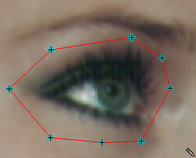
The Toolbox control should still have the Control Point tool selected. If it does not have the Control Point tool selected, please select it at this time. Now, drop Control Points all around the edge of the eye on the start image. About eight Control Points should be fine. Looking at the end image, the same Control Points should be visible; just leave them alone for the moment. When we do this, we place the Control Points as follows; one at each corner of the eye; one directly above, and one directly below the pupil; and the final four, one at a time, between the corners of the eye and the Control Points by the pupil:
Now we're going to add Links. Select the Links button located in the Toolbar.
You'll notice that when you click on the Link button, it looks as though it has been pressed down and stays that way. In Morph this is known as a state button. A state button will remain in its current position or state until selected again. In most cases when the button is down, the option is on, and vice versa.
Left clicking on the Links state button has turned on the Linking in Morph. Control Points (and within, but not between, other control Objects) can be linked by simply left clicking on the Control Point or Objects to be linked, and then left clicking on the next Control Point or Object point to be linked. You can proceed in this fashion until all of the desired Control Points or lines have been linked. It is important to note that you do not have to Link control Objects together, but linking can help you to better visualize how a morph will look and will give you greater control.
In the start image, beginning with any Control Point you like, click on each point in turn all the way around the eye. As you go, you'll see blue Links appear between each point. Continue until the eye is completely surrounded by Links. When you get to the last point, click on it twice to de-select it. Looking over at the end frame, you'll see the Links are there as well:
Now, we will de-select the Links state button, so that we can move the points and links without creating new Links. This can be done by left clicking on the Links button in the Toolbar. This will turn the Linking mode off.
We are now ready to move the Control Points and Links in the End image to create a warping effect. In the End image, move each of the Control Points in turn away from the eye — we're going to make the eye swell up.
This is done by right clicking on the desired Control Point, moving the mouse to the new position, and then releasing the right mouse button. Morph will then place the Control Point in the End image in the new location. Any Links that are attached to the Control Point will be automatically stretched to the proper length. Continue to move all of the Control Points in the End image in this manner. Adjust each of the Control Points in turn until the outline is about the same shape as the outline in the Start image, but larger:
Let's see how these new Control Points and Links affects the morph. The frame can be generated by selecting the Do one frame... option from Generate menu. Morph will now re-generate the preview frame.
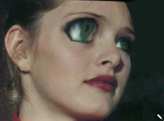
When the preview completes, you should have an image of a face with a somewhat distorted "enlarged" eyeball staring at you. The distortion arises because the Control Points and Links are not moved away from the original positions in a perfectly circular manner; this is something you definitely want to keep in mind, because you may be looking for this specific type of distortion, that is, a non-linear distortion, with many morphing projects. Here's the result we got:
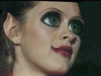
Now repeat this process using the Ellipse or Spline tools to place a continuous Ellipse or Spline around the eye, and then edit the end image line so that it is enlarged. Ellipses are particularly good for more linear distortions, and they're very easy to work with. You just draw out an Ellipse in the Start Frame, and then one in the End Frame. You can adjust them afterwards using the Move tool if you need to.
Here's how Ellipses help with getting smoother results:
In this manner you can familiarize yourself with all of the Object tools available, and how they interact.
More complex morphs are usually made up of several regions such as the one you just created around the eye. As is the case with many things, even the most complex morph is the sum of a series of simpler operations.
Have any Problems?
If you didn't get the results described here, we suggest you go back and go through the tour again. Most likely, you've missed a step somewhere.
, Previous Page . Next Page t TOC i Index o Operators g Glossary
Copyright © 1992-2007 Black Belt Systems ALL RIGHTS RESERVED Under the Pan-American Conventions
WinImages F/x Manual Version 7, Revision 6, Level A
